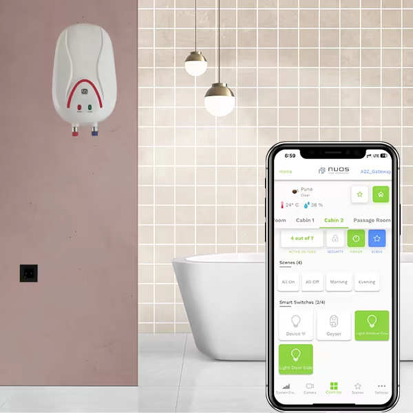
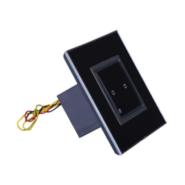
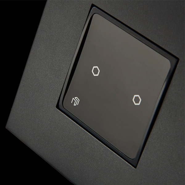
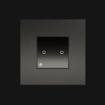
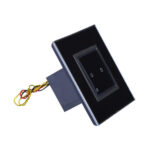
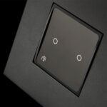
Zigbee Touch Switch 1 Relay 16 Amps offers Remote as well as Manual Control with On & Off of 1 Device/Circuit and High Wattage 16 Amps Device/Circuit. Schedule as well as base your needs and requirements. It’s Cloud Connected, Secure & Easy to Set Up.
Works with Android & iOS User Applications and is compatible with Amazon Alexa, Google Home & Apple Watch.
It’s Smart, Modular and Easy to Install.
| Dimensions | 45 mm x 48 mm x 45 mm |
| Weight | 100 g |
| Power Output |
Load 1: Drives up to 2A (500W Resistive) (non-dimmable) Load 2: Drives up to 16A (3680W Resistive) (non-dimmable) |
| Power Supply | 85 - 265 V AC, 50 - 60 Hz, 1ph |
|
Networking Interface |
Built in 2.4 GHz Zigbee variants available |
| Buttons | 2 Touch Buttons for controlling 2 individual non-dimmable loads (on/off control) |
| Power Method | Communicates with up to 6 wireless touch switches in the same room |
| Antennas 2.4 GHz | Internal PCB Antenna |
| Wireless Security | Supports AES 128-bit Encryption |
| Data Rate | Supports wireless data rates of up to 250 kbitps |
| Mounting | Snaps into switch plate |
| Operating Temperature | -20°C to 60°C |
| Operating Humidity | -20°C to 60°C |
| Certifications | RoHS, CE Class A Compliance (Self Declaration) |
Applications
Configuration
Applications
- Has in-built Zigbee and acts as a repeater for Zigbee Mesh Network.
- Inductive or Resistive Load Type (Switch 1 -2A and Switch 2 -16A).
- Can be accessed in dual mode local only through the same WiFi network as well as through cloud from anywhere in the world for seamless connectivity using Android and iOS Application.
- Supports unlimited (limited by mobile device memory) mood/scene/favorite profile setting through one click
- Supports up to 8 schedules/alarms on devices on and off for automatic device control.
- Supports renaming device names individually on each mobile/user device.
- Supports change of settings through cloud from anywhere in the world.
Configuration
- Please check NUOS Zigbee Gateway configuration for setting up and configuring the gateway.
- Push the NUOS Touch 1R16 inside the switch plate till it snap fits.
- Connect the Red Wire from behind the switch to the Line/Live wire of the electrical circuit.
- Connect the Black Wire from behind the switch to the Neutral wire of the electrical circuit.
- Connect the 2 Yellow Wires to the loads.
- Make sure the wiring connections are tightly secured by insulation/electrical tape to above lose connections and arcing behind switchboard.
- Close the switch board once the wiring is completed.
- New switches and sensors automatically associate with the gateway on power-up and can be added in the desired room using the user application.


